Thermal management is one of the most important design considerations for high-power electronic products. When components generate heat continuously, an aluminum PCB must provide an efficient thermal path to transfer heat away from the device and maintain stable operating temperatures.
The thermal resistance of an aluminum PCB stackup is calculated by analyzing the complete heat transfer path, including the component interface, dielectric layer, aluminum base layer and external cooling structure.
Unlike standard FR-4 PCBs, aluminum PCBs (also called metal core PCBs or MCPCBs) use a metal base layer to improve heat dissipation. However, the thermal performance of an aluminum PCB does not depend only on the aluminum core. Every layer in the stackup contributes to the total thermal resistance.
Engineers need to evaluate:
- dielectric layer thermal conductivity;
- dielectric thickness;
- aluminum base thickness;
- copper layer structure;
- component heat generation;
- external cooling conditions.
This article explains the thermal resistance calculation method for aluminum PCB stackups and the design factors that influence heat dissipation performance.
Understanding Thermal Resistance in Aluminum PCBs
Thermal resistance describes how effectively a structure transfers heat.
It is usually expressed as:
°C/W (degrees Celsius per Watt)
A lower thermal resistance means heat can travel through the structure more efficiently.
The basic relationship is:
Thermal Resistance = Temperature Difference / Heat Flow
Formula:
Rθ = ΔT / P
Where:
- Rθ = thermal resistance (°C/W)
- ΔT = temperature difference (°C)
- P = power dissipation (W)
For an aluminum PCB, heat travels through multiple layers before reaching the surrounding environment.
A typical thermal path includes:
- Semiconductor junction
- Component package
- Solder interface
- Copper layer
- Dielectric insulation layer
- Aluminum base layer
- Heat sink or enclosure
Each layer adds some thermal resistance.
Why Aluminum PCB Thermal Resistance Matters
High-power electronic products often face thermal challenges because excessive temperature can affect:
- component lifetime;
- electrical performance;
- system reliability;
- safety margins.
Applications using aluminum PCBs include:
- LED lighting systems;
- power converters;
- automotive electronics;
- industrial control equipment;
- motor control systems.
Thermal Problems Caused by Poor Heat Management
| Problem | Possible Impact |
| High junction temperature | Reduced component lifetime |
| Thermal stress | Material fatigue |
| Uneven heat distribution | Local overheating |
| Excessive temperature rise | Performance degradation |
The purpose of aluminum PCB thermal design is not only to remove heat but also to maintain a stable temperature distribution across the entire circuit.
Thermal Resistance Model of an Aluminum PCB Stackup
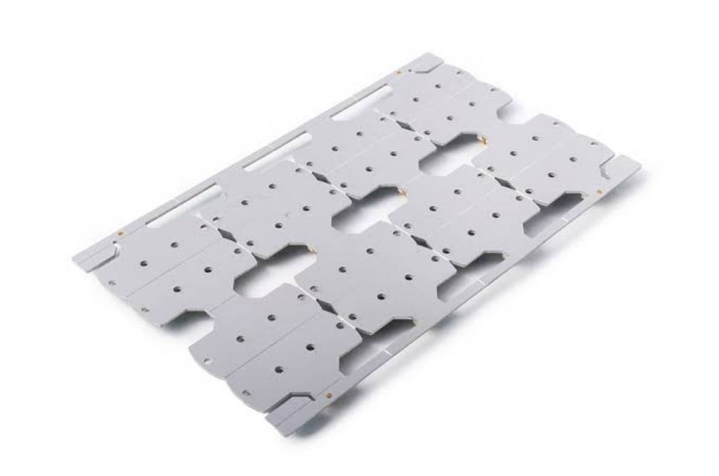
A typical aluminum PCB contains three major functional layers:
| Layer | Main Function |
| Copper layer | Electrical connection and current carrying |
| Dielectric layer | Electrical insulation and thermal transfer |
| Aluminum base | Mechanical support and heat spreading |
Among these layers, the dielectric layer usually has the greatest influence on thermal resistance because it must provide electrical isolation while allowing heat transfer.
How to Calculate Thermal Resistance of Each Layer
The thermal resistance of a single layer can be calculated using:
Rθ = L / (k × A)
Where:
- L = material thickness (m)
- k = thermal conductivity (W/m·K)
- A = heat transfer area (m²)
Example Layer Calculation
| Parameter | Meaning |
| Material thickness | Distance heat travels |
| Thermal conductivity | Ability to transfer heat |
| Area | Heat spreading region |
A thinner layer with higher thermal conductivity generally produces lower thermal resistance.
The Complete Thermal Resistance Path
In an aluminum PCB stackup, total thermal resistance is approximately the sum of each layer resistance:
Rtotal = R1 + R2 + R3 + …
A simplified thermal path may include:
| Section | Thermal Resistance Contribution |
| Component interface | Depends on package design |
| Copper layer | Usually relatively low |
| Dielectric layer | Often the dominant factor |
| Aluminum base | Provides heat spreading |
| External interface | Depends on cooling design |
The final thermal performance depends on the entire system rather than one material.
Key Factors Affecting Aluminum PCB Thermal Resistance
1. Dielectric Layer Thickness
The dielectric layer is critical because it separates copper from aluminum while transferring heat.
A thicker dielectric layer provides:
- stronger insulation;
- higher voltage capability.
However, it also increases thermal resistance.
Thickness Impact
| Dielectric Thickness | Thermal Effect |
| Thin layer | Better heat transfer |
| Thick layer | Higher thermal resistance |
| Optimized thickness | Balance between insulation and cooling |
Designers should select dielectric thickness based on both electrical safety and thermal requirements.
2. Dielectric Thermal Conductivity
Thermal conductivity determines how easily heat passes through the insulating layer.
Higher conductivity materials allow heat to move more efficiently.
Thermal Conductivity Comparison
| Dielectric Property | Result |
| Higher thermal conductivity | Lower thermal resistance |
| Lower thermal conductivity | Slower heat transfer |
For high-power applications, dielectric material selection becomes an important thermal design decision.
3. Aluminum Base Thickness
The aluminum layer provides:
- mechanical strength;
- heat spreading capability;
- thermal stability.
Increasing aluminum thickness may improve heat spreading, but the overall improvement depends on the complete thermal path.
Aluminum Base Considerations
| Factor | Effect |
| Thin aluminum layer | Lower weight, limited spreading |
| Thick aluminum layer | Better mechanical support |
| Proper thickness | Balanced design |
The aluminum base should match the power level and application environment.
4. Copper Layer Design
Although copper mainly provides electrical conductivity, it also influences heat distribution.
Large copper areas can help spread heat before it reaches the dielectric layer.
Important considerations include:
- copper thickness;
- copper coverage;
- thermal pad design;
- connection between component pads and thermal paths.
Aluminum PCB Thermal Resistance vs FR-4 PCB
| Feature | Aluminum PCB | FR-4 PCB |
| Base material | Aluminum metal core | Glass epoxy |
| Thermal performance | Higher | Lower |
| Heat spreading | Excellent | Limited |
| High-power suitability | Strong | More limited |
| Typical applications | LEDs, power electronics | General electronics |
Aluminum PCBs are often selected when thermal management is a primary design requirement.
Thermal Design Example for LED Aluminum PCB
LED applications are one of the most common uses of aluminum PCBs.
An LED generates heat at the semiconductor junction.
The heat path is:
LED junction
→ LED package
→ solder pad
→ copper layer
→ dielectric layer
→ aluminum core
→ heat sink/environment
Any bottleneck in this path increases junction temperature.
LED Thermal Design Factors
| Factor | Importance |
| Thermal pad design | Improves heat transfer |
| Dielectric conductivity | Reduces thermal resistance |
| Aluminum base | Spreads heat |
| External cooling | Removes final heat |
Proper thermal design helps maintain LED efficiency and reliability.
Common Mistakes in Aluminum PCB Thermal Design
Mistake 1: Only Considering Aluminum Thickness
Many designers assume a thicker aluminum base automatically solves thermal problems.
However, the dielectric layer and thermal interface often have a larger impact.
Mistake 2: Ignoring Thermal Interface Resistance
Even a well-designed PCB can perform poorly if the connection to:
- heat sinks;
- enclosures;
- cooling systems
is not optimized.
Mistake 3: Using Electrical Design Rules Only
Thermal performance must be considered together with:
- current density;
- component placement;
- heat distribution.
Mistake 4: Overlooking Heat Spreading Area
Small thermal areas may create local hotspots.
Designers should consider:
- copper coverage;
- component spacing;
- aluminum base area.
How to Improve Aluminum PCB Thermal Performance
Several approaches can reduce thermal resistance:
Optimize Dielectric Material
Select dielectric materials with suitable:
- thermal conductivity;
- thickness;
- insulation capability.
Improve Thermal Path Design
Reduce unnecessary barriers between:
- heat source;
- copper layer;
- aluminum base;
- external cooling structure.
Optimize Component Placement
Place high-power components where heat can be effectively distributed.
Work With an Experienced Aluminum PCB Manufacturer
Manufacturing capability affects:
- dielectric consistency;
- layer bonding quality;
- dimensional stability;
- thermal performance.
Mars-PCB provides aluminum PCB manufacturing solutions for applications requiring efficient thermal management and reliable metal core PCB structures.
How to Select an Aluminum PCB Manufacturer
When choosing an aluminum PCB supplier, engineers should evaluate:
| Capability | Why It Matters |
| Thermal material experience | Supports correct material selection |
| Stackup design capability | Improves thermal performance |
| Manufacturing consistency | Reduces quality variation |
| Application experience | Helps solve thermal challenges |
| Engineering support | Improves design efficiency |
A good supplier should understand both electrical requirements and thermal performance goals.
For more information about Mars-PCB capabilities, visit the Mars-PCB website.
FAQ
How do you calculate aluminum PCB thermal resistance?
Aluminum PCB thermal resistance is calculated by analyzing each layer in the heat path using the formula Rθ = L/(k×A), then adding the resistance of each layer.
What layer has the biggest impact on aluminum PCB thermal resistance?
The dielectric layer usually has the greatest influence because it must balance electrical insulation with thermal conductivity.
Why are aluminum PCBs better for heat dissipation?
Aluminum PCBs use a metal core that spreads heat more effectively than traditional FR-4 materials.
How does dielectric thickness affect MCPCB thermal resistance?
A thicker dielectric layer generally increases thermal resistance because heat must travel through a longer insulating path.
What applications require low thermal resistance PCBs?
Applications such as LED lighting, power electronics, automotive systems and industrial equipment often require low thermal resistance PCB structures.
Can aluminum PCB replace FR-4 PCB?
Aluminum PCB is suitable for heat-sensitive applications but may not replace FR-4 in applications where flexibility, cost or complex multilayer routing is more important.