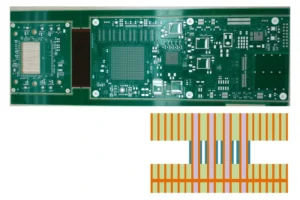
Microwave PCB fabrication is challenging because high-frequency circuit boards are sensitive to material loss, dielectric thickness variation, copper roughness, impedance deviation, via discontinuity, and dimensional tolerance. At microwave frequencies, the PCB is no longer just a mechanical base for components; it becomes an active part of the signal path.
A microwave circuit board must preserve signal quality across transmission lines, RF transitions, filters, couplers, antennas, amplifiers, and interconnects. If the material, stackup, etching, copper surface, drilling, or surface finish is not controlled properly, the final board may show higher insertion loss, poor return loss, frequency shift, unstable impedance, or inconsistent performance between batches.
For engineers, the key question before ordering is not only “Can this factory make microwave PCBs?” The better question is: can the supplier control the fabrication variables that affect microwave performance?
Mars-PCB provides microwave PCB fabrication support for RF and high-frequency circuit boards that require low-loss materials, controlled impedance, and manufacturing review before production.
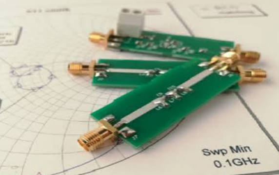
The Real Difference Between Microwave PCBs and Standard PCBs
Standard PCBs are usually evaluated by connectivity, solderability, layer registration, mechanical dimensions, and general reliability. Microwave PCBs must meet those requirements too, but the tolerance window is much narrower because the electrical behavior is tied directly to the physical board structure.
In a microwave PCB, a trace is not just copper. It is a transmission line. The dielectric under the trace, the ground plane distance, copper profile, solder mask, via transition, and surface finish all influence how energy moves through the board.
In microwave PCB manufacturing, a small physical variation can become a measurable RF performance shift.
That is why microwave PCB fabrication should begin with an engineering review of material, stackup, impedance, and layout-critical areas before the board enters production.
Challenge 1: Choosing a Material That Matches the Frequency and Loss Budget
Microwave PCB materials are selected mainly for electrical stability. The two most discussed values are dielectric constant and dissipation factor.
Dielectric constant, often called Dk, affects impedance, wavelength, phase velocity, and physical trace geometry. Dissipation factor, often called Df, affects dielectric loss. In microwave circuits, lower loss is often preferred, but material selection should not be based on one number alone.
Common microwave PCB material categories include:
| Material Category | Common Use in Microwave PCB Fabrication | Engineering Consideration |
| Rogers laminates | RF, microwave, radar, antenna, and communication circuits | Good high-frequency material options, but exact grade must match the design |
| PTFE-based materials | Low-loss microwave and RF circuits | Strong RF performance potential, but fabrication can be more demanding |
| Ceramic-filled PTFE | Microwave circuits requiring stable electrical behavior | Useful for stability, but process compatibility should be checked |
| Taconic materials | RF and microwave applications | Material grade, thickness, and copper option should be confirmed |
| Isola low-loss materials | High-speed and some RF/microwave boards | Often relevant for mixed RF and high-speed digital systems |
| High-frequency FR-4 alternatives | Cost-sensitive lower-frequency designs | Must be checked carefully for loss and Dk stability |
The mistake many teams make is starting with a famous material name instead of the actual performance requirement. For example, saying “we need Rogers” is less useful than defining frequency range, target impedance, acceptable insertion loss, dielectric thickness, copper weight, and stackup structure.
A microwave PCB material should be selected by frequency, loss target, impedance structure, thermal environment, and fabrication capability—not by brand name alone.
Challenge 2: Keeping Dielectric Thickness Stable
Dielectric thickness is one of the most important variables in microwave PCB fabrication. It determines the distance between the signal trace and the reference plane. That distance directly affects impedance.
For microstrip routing, the RF trace is usually on the outer layer with a ground plane below. For stripline routing, the trace is embedded between reference planes. In both cases, dielectric thickness affects the required trace width and the final impedance.
If the fabricated dielectric thickness differs from the assumed design value, the impedance may shift. If the impedance shifts, the circuit may show reflection, mismatch, or changed frequency response.
Important dielectric questions include:
| Question | Why It Matters |
| What laminate thickness is actually available? | Design values must match manufacturable material |
| Is the thickness tolerance acceptable? | Variation affects impedance repeatability |
| Is this a core or prepreg-controlled layer? | Prepreg flow can affect final thickness |
| Is this a hybrid stackup? | Different materials may behave differently during lamination |
| Is the RF trace on an outer or inner layer? | Field structure and impedance calculation change |
For microwave projects, the stackup should be approved before final routing. If the supplier changes material thickness after layout, the RF line width may need to change too.
Challenge 3: Controlling Copper Roughness and Conductor Loss
At microwave frequencies, current tends to flow near the surface of the conductor. This makes copper surface condition more important than in low-frequency PCB designs.
Copper roughness can increase conductor loss. It may also influence insertion loss consistency across long RF paths. For short or lower-frequency traces, the impact may be manageable. For microwave, millimeter-wave, radar, and high-speed RF circuits, copper roughness deserves early attention.
Key copper-related checks include:
- Base copper type
- Finished copper thickness
- Copper roughness profile
- Low-profile copper availability
- Plating buildup
- Etching compensation
- Surface treatment process
- Whether impedance calculation uses finished copper thickness
For microwave PCBs, copper is not only a conductor; its surface profile can affect signal loss.
This is especially important when the circuit has long transmission lines, tight loss budgets, high operating frequency, or sensitive phase requirements.
Challenge 4: Maintaining Controlled Impedance After Etching
Controlled impedance is a core requirement in many microwave circuit boards. Common structures include 50-ohm microstrip, stripline, grounded coplanar waveguide, and other RF transmission line forms.
The challenge is that calculated impedance is not the same as fabricated impedance. The final impedance depends on actual material thickness, final copper thickness, trace width after etching, solder mask condition, and local copper geometry.
| Variable | Effect on Microwave PCB Impedance |
| Trace width | Changes characteristic impedance |
| Dielectric thickness | Changes distance to reference plane |
| Dk value | Affects field propagation and impedance |
| Copper thickness | Changes effective trace geometry |
| Etching tolerance | Changes final line width |
| Solder mask | Can affect outer-layer transmission lines |
| Ground gap | Critical for coplanar waveguide structures |
| Plating | Affects finished conductor dimensions |
A practical microwave PCB fabrication package should include an impedance table. It should define signal layer, target impedance, tolerance, trace width, spacing, reference plane, material, and whether impedance test coupons are required.
Challenge 5: Handling Microstrip, Stripline, and Coplanar Structures Correctly
Different microwave PCB transmission line structures create different manufacturing risks.
| Structure | Main Advantage | Fabrication Risk |
| Microstrip | Easy to access and inspect; common for RF routing | Sensitive to solder mask, surface copper, and dielectric thickness |
| Stripline | Better field containment and shielding | Requires accurate lamination and inner-layer registration |
| Grounded coplanar waveguide | Good field control in compact RF layouts | Sensitive to gap width, via fence spacing, and plating |
| Coplanar waveguide | Useful for specialized RF circuits | Requires precise same-layer spacing control |
| PCB antenna structure | Can reduce module size | Highly sensitive to copper geometry and material stability |
Microwave PCB layouts often contain more than one structure. For example, a board may use microstrip for connector launches, grounded coplanar waveguide for compact RF routing, and stripline for shielded internal paths. Each structure should be identified during DFM review.
The manufacturer should know which traces are RF-critical. Otherwise, an area may be treated as normal copper routing when it actually controls impedance, phase, or antenna behavior.
Challenge 6: Avoiding Via Discontinuities
Vias can create discontinuities in microwave PCB circuits. At lower frequencies, a via may behave like a simple vertical interconnect. At microwave frequencies, the via has inductance, capacitance, and possible stub effects.
Via-related challenges include:
- Signal via geometry
- Ground via placement
- Via fence spacing
- Back-drilling requirements
- Blind or buried via feasibility
- Via stub length
- Pad and antipad design
- Layer transition symmetry
- Hole wall plating quality
In grounded coplanar waveguide structures, via fences may be used to connect top-layer ground to internal or bottom ground planes. If the via spacing is poorly designed or not fabricated consistently, shielding and field control may be weaker than expected.
In microwave circuit boards, vias should be treated as RF structures, not only as electrical connections.
Challenge 7: Managing Surface Finish Without Hurting RF Behavior
Surface finish is often discussed for solderability, but in microwave PCBs it may also influence RF behavior depending on frequency, conductor exposure, and circuit structure.
Common surface finishes include ENIG, immersion silver, OSP, immersion tin, and other options depending on the manufacturer’s process capability. The right choice depends on assembly method, shelf-life requirement, component type, RF contact requirement, and frequency sensitivity.
Important questions include:
| Surface Finish Question | Why It Matters |
| Is the finish compatible with assembly? | Ensures solderability and component reliability |
| Does the RF path include exposed copper areas? | Finish may affect conductor surface behavior |
| Are RF connectors or edge contacts involved? | Surface finish and flatness may matter |
| Is wire bonding required? | Finish selection becomes more specific |
| Is long storage expected? | Oxidation resistance may be important |
There is no single finish that is correct for all microwave PCBs. The finish should be selected according to the circuit function and assembly process.
Challenge 8: Combining RF, Digital, and Power Sections on One Board
Many microwave boards are not pure RF boards. They may include RF front-end circuits, digital control, power management, bias networks, processors, connectors, and sometimes antennas.
This creates mixed-design challenges:
- RF traces need stable reference planes
- Digital traces can create noise coupling
- Power circuits can inject switching noise
- Ground regions must be planned carefully
- Thermal paths must not disturb RF fields
- Layer transitions must avoid RF discontinuities
- Shielding may be required between functional blocks
For complex boards, the PCB stackup should separate RF-critical paths from noisy digital and power sections. Ground planes, via stitching, shielding, and component placement should be planned together.
Challenge 9: Preserving Dimensional Accuracy for Microwave Features
Microwave circuits may include filters, couplers, resonators, matching networks, antenna feeds, and other geometry-sensitive copper structures. These features are not just routing shapes. Their dimensions are part of the circuit behavior.
Fabrication accuracy matters for:
- Trace width
- Gap spacing
- Copper length
- Pad geometry
- Antenna dimensions
- Edge-to-copper distance
- Layer alignment
- Slot or cavity features
- Connector launch geometry
If these features are not identified as RF-critical, they may not receive enough attention during fabrication review.
A practical approach is to mark RF-critical regions in the fabrication notes or communicate them during DFM review. This helps the manufacturer understand where dimensional control is most important.
Microwave PCB Fabrication Review Checklist
Before sending a microwave PCB to production, engineers should prepare a complete fabrication package.
| Item | What to Define |
| Material | Laminate type, Dk, Df, thickness, copper option |
| Stackup | Layer order, dielectric thickness, copper thickness |
| Controlled impedance | Target impedance, tolerance, layer, trace width, spacing |
| RF-critical areas | Filters, antennas, launch structures, long RF paths |
| Transmission line type | Microstrip, stripline, GCPW, CPW |
| Via strategy | Signal vias, ground vias, via fences, back-drilling if needed |
| Surface finish | Assembly and RF requirements |
| Solder mask | Mask over or away from RF traces |
| Copper requirements | Finished thickness, roughness consideration, plating notes |
| Test requirements | Electrical test, impedance test, inspection requirements |
| Production phase | Prototype, pilot run, or batch production |
For high-frequency projects, Mars-PCB can provide RF microwave PCB manufacturing review to help engineers check material, stackup, impedance, and DFM risks before fabrication.
What Makes a Supplier Suitable for Microwave PCB Manufacturing?
A suitable microwave PCB supplier should understand how fabrication choices affect RF performance. The supplier should be able to review more than line width and spacing. They should discuss stackup, material compatibility, dielectric thickness, impedance, copper profile, via structures, and test requirements.
Before ordering, ask the supplier:
- Can you process the specified microwave PCB material?
- Can you confirm available laminate thickness and copper type?
- Can you calculate impedance based on the actual manufacturable stackup?
- Can you support microstrip, stripline, or grounded coplanar waveguide structures?
- Can you review RF-critical copper features before production?
- Can you provide impedance coupons if needed?
- Can you control finished copper thickness?
- Can you support hybrid RF/digital stackups?
- What surface finish do you recommend for this application?
- What DFM risks do you see in this microwave PCB design?
For broader project needs, engineers can also review Mars-PCB custom PCB manufacturing when planning fabrication, assembly, or production support.
FAQ
What is microwave PCB fabrication?
Microwave PCB fabrication is the manufacturing of printed circuit boards designed for microwave-frequency circuits. It requires low-loss materials, controlled impedance, stable dielectric thickness, precise copper geometry, and careful via and surface finish control.
What materials are used for microwave circuit boards?
Common microwave circuit board materials include Rogers laminates, PTFE-based materials, ceramic-filled PTFE, Taconic materials, Isola low-loss laminates, and selected high-frequency FR-4 alternatives. The correct material depends on frequency, loss budget, stackup, and cost target.
Why is copper roughness important in microwave PCB manufacturing?
Copper roughness can increase conductor loss at high frequencies because current flows near the conductor surface. In microwave PCB manufacturing, smoother or low-profile copper may be considered when insertion loss and phase stability are critical.
How does dielectric thickness affect microwave PCB performance?
Dielectric thickness affects impedance, trace width, signal velocity, and repeatability. If the actual fabricated thickness differs from the design assumption, the microwave PCB may show impedance mismatch or changed RF behavior.
What is the difference between RF PCB and microwave PCB?
RF PCB is a broad term for radio-frequency circuit boards. Microwave PCB usually refers to boards operating at higher RF frequencies where material loss, copper roughness, impedance control, and dimensional tolerance become especially important.
Can FR-4 be used for microwave PCB fabrication?
FR-4 may be used in some lower-frequency or non-critical sections, but many microwave circuits require lower-loss high-frequency materials. The decision should be based on operating frequency, insertion loss, impedance stability, and reliability requirements.
What should I send to a microwave PCB manufacturer before fabrication?
You should send Gerber or ODB++ files, drill files, stackup drawing, material requirements, impedance table, RF-critical area notes, solder mask requirements, via requirements, surface finish, and test requirements.
Conclusion
Microwave PCB fabrication is difficult because the physical board structure directly affects high-frequency circuit behavior. Material loss, dielectric thickness, copper roughness, trace accuracy, via transitions, solder mask, surface finish, and stackup design all influence final performance.
For engineers, the safest workflow is to confirm material and stackup first, identify RF-critical areas, define controlled impedance requirements, and request DFM review before fabrication. This reduces the risk of signal loss, impedance mismatch, prototype failure, and inconsistent production results.
Mars-PCB supports microwave PCB fabrication for high-frequency circuit boards that require RF material selection, controlled impedance support, and practical manufacturing review.