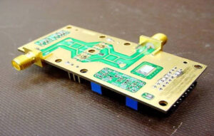
In the world of advanced electronics, the substrate of a Printed Circuit Board (PCB) is no longer just a passive mechanical support. As signal speeds climb into the gigahertz range, the material itself becomes a critical component that dictates whether a product succeeds in the lab or fails in the field.
At Mars-PCB, we often tell our clients that choosing the right material is like choosing the DNA for your device. If the foundation is flawed, no amount of clever routing or high-end components can fully compensate for the signal degradation that follows. Whether you are an engineer striving for signal integrity or a buyer balancing the bottom line, understanding the nuances of high-speed PCB laminates is essential.
I. The Technical Foundation: Understanding Dk and Df
When evaluating materials for high-speed applications, two parameters stand above all others: the Dielectric Constant (Dk) and the Dissipation Factor (Df).
1. Dielectric Constant (Dk / $\varepsilon_r$)
The Dielectric Constant measures how much electrical energy the material can store. More importantly for designers, it dictates how fast a signal travels through the copper traces.
The Dielectric Constant (Dk) of a PCB material directly influences signal propagation speed and characteristic impedance; a lower and more stable Dk is preferred for high-speed designs to minimize propagation delay and ensure consistent impedance across varying frequencies.
If the Dk fluctuates across the board or across different frequencies, your signals will arrive at different times—a nightmare for high-speed data buses like DDR4 or PCIe 5.0.
2. Dissipation Factor (Df / Tan $\delta$)
If Dk is about speed, Df is about “leakage.” It represents the amount of energy lost as heat within the dielectric material as the signal travels.
The Dissipation Factor (Df) is the primary indicator of signal loss in high-frequency circuits; choosing a low-loss laminate with a Df below 0.005 is critical for maintaining signal amplitude and edge rates over long trace lengths.
II. The Material Hierarchy: Navigating the Tiers
Not every high-speed board requires the most expensive space-grade laminate. At Mars-PCB, we categorize materials into four main tiers to help you find the “sweet spot” for your application.
Comparison Table: High-Speed PCB Material Tiers
| Tier | Representative Materials | Typical Df (@10GHz) | Best Use Case | Cost Index |
| Standard FR-4 | IT-180A, S1170 | 0.015 – 0.020 | Below 1 GHz / Low cost | $ |
| Mid-Loss | Nelco N4000-13, IT-170GRA1 | 0.008 – 0.012 | 1 – 5 GHz / Networking | $$ |
| Low-Loss | Panasonic Megtron 6, Isola TerraBA | 0.002 – 0.004 | 10 – 28 GHz / 5G / Servers | $$$ |
| Ultra-Low Loss | Rogers 4350B, Taconic FastRise | < 0.002 | 30+ GHz / Radar / RF |
When to Upgrade from FR-4?
Standard FR-4 is perfectly fine for many applications. However, once your data rates exceed 3 Gbps or your frequencies go above 1 GHz, the “dielectric absorption” of FR-4 begins to round off your digital pulses, leading to bit errors. This is the point where a conversation with the Mars-PCB engineering team becomes vital to prevent prototype failure.
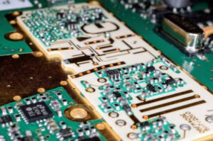
III. Thermal and Reliability Factors: Beyond Signal Speed
While engineers focus on Dk/Df, buyers and manufacturing experts must look at how the material handles heat. High-speed chips run hot, and the assembly process (reflow soldering) is even hotter.
1. Glass Transition Temperature (Tg)
Tg represents the temperature at which the base laminate transitions from a rigid, “glassy” state to a more flexible, “rubbery” state; for high-speed PCBs, a High-Tg material (above 170°C) is necessary to ensure mechanical stability during multi-stage lead-free soldering.
2. Coefficient of Thermal Expansion (CTE)
As the board heats up, it expands. If the material expands too much in the Z-axis (thickness), it can actually snap the copper vias that connect the layers.
- Low Z-axis CTE: Essential for high-layer-count boards (12+ layers) to prevent “via cracking” during thermal cycling.
3. Thermal Conductivity
If your design includes high-power components, look for materials with high thermal conductivity (measured in W/m/K). This allows the board to act as a giant radiator, pulling heat away from sensitive silicon.
IV. Addressing the “Glass Weave Effect”
This is a subtle technical trap that catches many designers by surprise. PCB laminates are made of woven glass fabric soaked in resin. Because glass and resin have different Dk values, a signal trace might run over a “bundle” of glass for a few inches and then over a “pocket” of resin.
The Glass Weave Effect causes intra-pair skew in high-speed differential pairs because the two traces of the pair experience different Dielectric Constants; using “spread glass” or “flat glass” fabrics ensures a more uniform dielectric environment.
At Mars-PCB, we recommend using glass styles like 1067 or 1086 for ultra-high-speed designs to eliminate this timing mismatch and ensure your differential pairs stay perfectly synced.
V. The Buyer’s Perspective: Managing Cost and Lead Time
In procurement, “the best material” is the one that meets performance specs without breaking the budget or causing a 12-week delay.
1. The Hybrid Stack-up Strategy
You don’t always need to build the entire board out of expensive Rogers material.
A Hybrid PCB Stack-up, which combines high-performance low-loss laminates for signal layers with standard FR-4 for power and ground layers, is the most cost-effective way to achieve high-speed performance while reducing overall material costs by 30% to 50%.
2. Lead Time and Availability
Exotic materials can have long lead times. At Mars-PCB, we maintain a consistent stock of Panasonic Megtron 6, Rogers 4350B/4003C, and Isola materials. If your design specifies a very niche material, our engineers can often suggest a “drop-in” equivalent that is more readily available and more affordable.
VI. Why Partner with Mars-PCB for Your Material Selection?
Choosing a material is a high-stakes decision. At Mars-PCB, we don’t just take your files and hit “print.” We offer:
- Pre-order Simulation Support: We help you model your impedance based on our actual measured Dk/Df values, not just datasheet theoreticals.
- Strict Material Traceability: We source only from authorized manufacturers to ensure your boards don’t suffer from “material substitution” issues.
- Advanced Lamination Control: High-speed resins require specific temperature and pressure profiles. Our facility is optimized for these sensitive “exotic” materials.
Core Points Summary (FAQ)
Q: What is the single most important factor for high-speed material?
A: Stability. You need a material where the Dk and Df remain constant across the entire operating frequency and temperature range of your device.
Q: Can I use FR-4 for a 10Gbps signal?
A: It is highly discouraged for traces longer than an inch or two. The signal loss will likely be too great for the receiver to decode the data. We suggest moving to a mid-loss or low-loss laminate.
Q: What does “Spread Glass” mean?
A: It refers to a glass weave where the fibers are flattened out to cover the gaps between the yarns. This creates a more uniform Dielectric Constant across the board surface.
Q: How does Mars-PCB handle hybrid stack-ups?
A: We use specialized bonding sheets (prepregs) that are compatible with both the high-speed laminate and the FR-4 core to ensure no delamination occurs during the board’s lifespan.
Q: Is Rogers material only for RF/Radio designs?
A: While famous for RF, Rogers 4000 series is excellent for digital high-speed designs (like 28Gbps+ backplanes) due to its superior thermal conductivity and low loss.